This is going to be very quick write-up, it’s been 6 months since I gave it to my kid as a Christmas present but I’m still updating the code and adding new features.
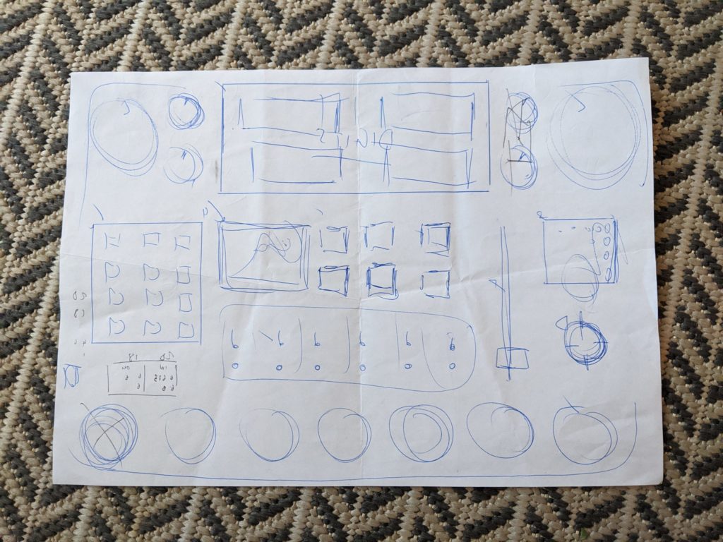
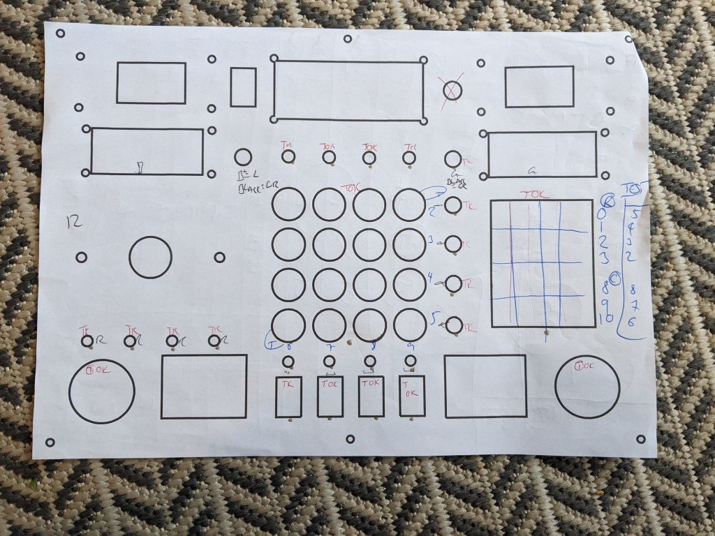
Designing the box surface.
First step here was to decide on the size and scale of the box surface and where all the buttons/switches and gizmos will go, It’s just under A4 at 210mm x 295mm. I spent a while on aliexpress and all the usual sites for buttons, switches, LEDs etc and then made paper templates from the datasheets and arranged manually. Once I was happy, I put in the order.
Most parts can be ordered on Amazon/Adafruit etc but mark up is crazy. If you can wait 1-2 months for delivery then aliexpress/banggood is your friend. While all this was on order I worked on the box.
Making the Box
I don’t know how to make boxes.
I decided on using the same method as my Bar Top arcade, wood and modesty blocks.
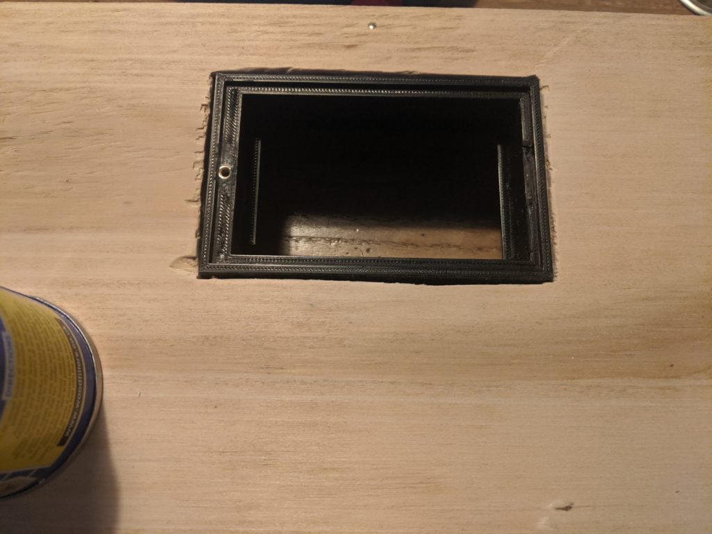
I ordered bottom/back and sides in 12mm plywood. Modesty blocks were used to construct but used up too much space inside so I glued & nailed and then removed the modesty blocks. I also hacked a hole in the bottom to fit a 3D printed battery compartment for the battery holder. All 3D files that I designed/printed personally are available on thingiverse.com (see links below).
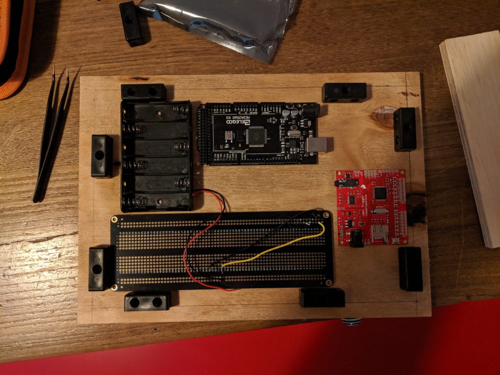
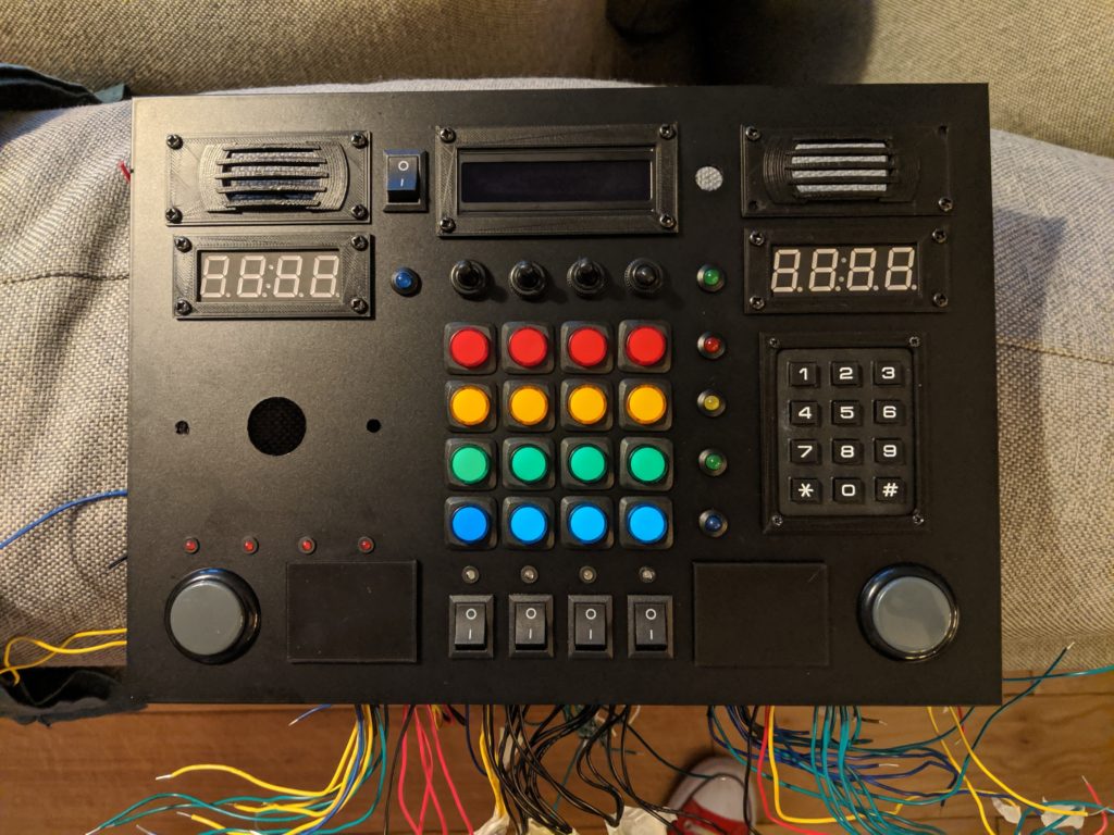
Sizing up the box and components prior to building the box.
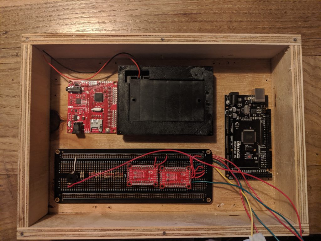
Box built, Main boards in final position
Hole cut in bottom of box, 3d Printed Battery box holder in place (with screw insert glued in place. Area was wood filled, sanded and painted.)
The box was wood filled and sanded. I attempted to prime and paint but it looked crap. I covered the the whole box in Matt Black Car Vinyl Wrap.
Surface design.
I found the issue with many components is they are not really suitable for surface mounting out of the box. To fix this I designed 3D printed holders/brackets that would screw into the main surface plate (more on that later). A painful process, some of the datasheets were far from accurate so it came down to measure, 3D print, test – repeat. I 3D printed a small portion of the surface and then test fit until happy. The 3D designs could themselves be used later in the final control panel (surface) build. This is what that all looks like…
Click to view on Thingiverse
The Electronics
There are a lot of inputs here. Too many for even an Arduino Mega so had to include some GPIO expanders, I made my life easier by using boards that are I2C controlled.
39 (24 Button/Switch inputs + 16 in matrix + 12 in matrix)
2 additional inputs for the capacative buttons
3 I2C connections
30 LEDs (should have had a dedicated LED controller)
Internal Electronics list.
Elgoo Arduino Mega Clone ( should have gone with the pro header-less version – would have been easier to solder.
Spark Fun Wav Trigger I tested a simple wav trigger board but latency was terrible and I wanted polyphonic so I sacrificed this board which I bought a while ago. If doing this again I would look at the teensy 3.2 with the audio board and library and a custom PCB.
Perf Board to tie it all together (LED resistors banks,capacitive touch circuit, GPIO expanders\ buzzer and also 3v and 5v power rails). You can see most of that in the box pic above.
Testing the Components
At this point I wired up all the components and tested them all out via individual sketches to make sure they worked as I wanted. I killed a red in black LCD and a keypad in the process.
The Capacative buttons (the two square panels each side of the rocker switches) are completely 3D printed, the undersides have two layers of tin-foil glued with a small insert for a screw which makes good contact with the foil. I don’t have a picture of these but you can check out the 3D model and should be able to work it out.
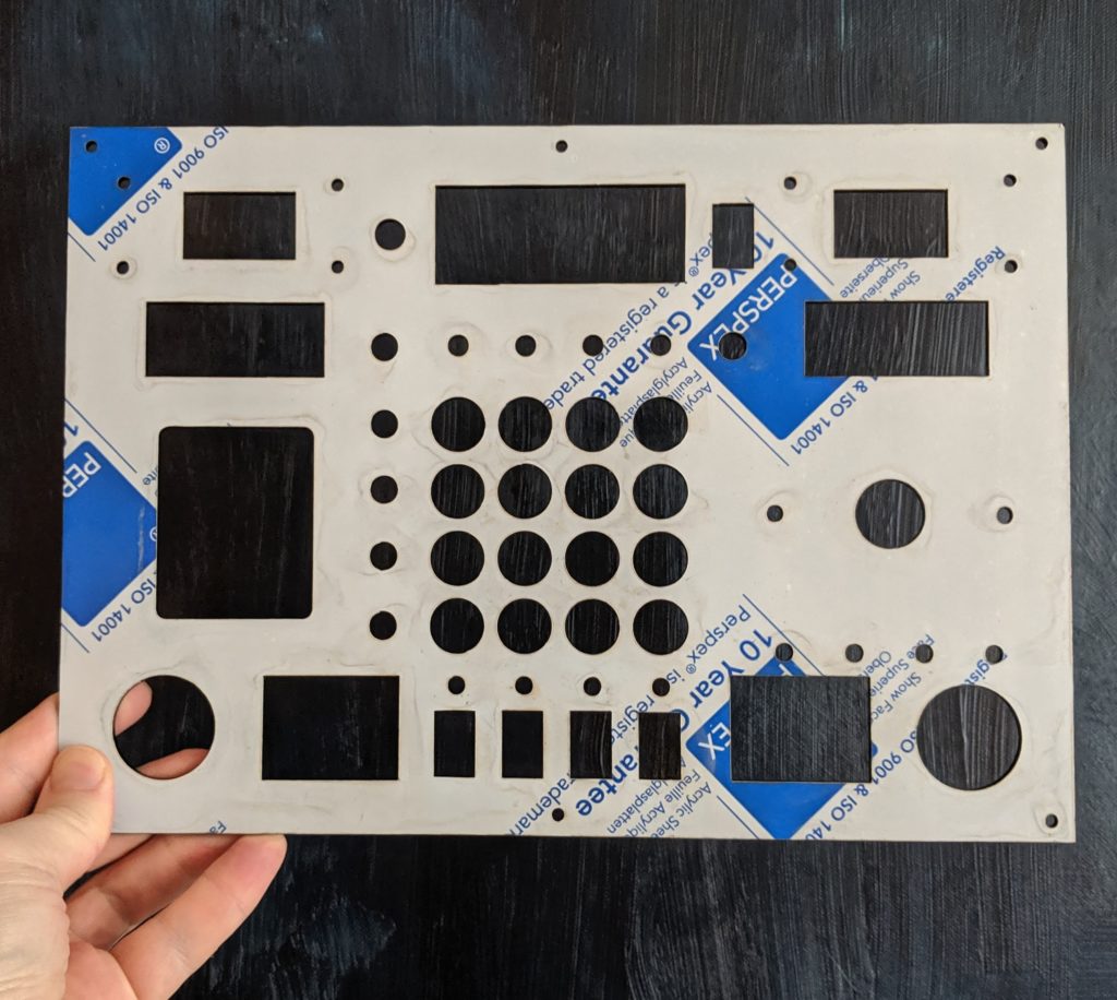
Originally I was going to 3D print this but then decided to LaserCut 3mm Black Acrylic. Never done this before but was easy enough, I already had all the holes/brackets designed so just a case of assembling all 3d elements into a single 3d design, flattening to 1mm, converting to SVG, coloring the cut lines and sending off to cut. I found a great company, cheap and helpful.
Print of the final SVG (lines enlarged for visability)
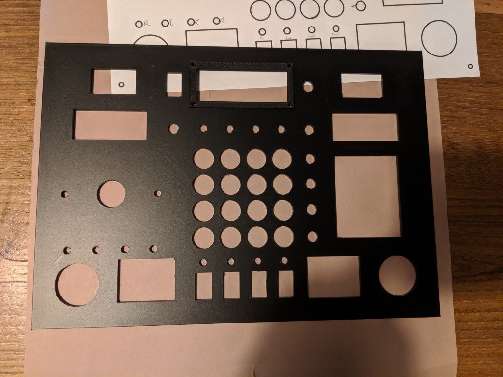
I had two printed, the above is the failure. I was hoping to glue the keypad in place but was not happy with the result so instead re-designed an internal and external holding bracket for the keypad which looked much better (see 3D files). The paper printed version above you’ll note has a larger square cut hole for the keypad..
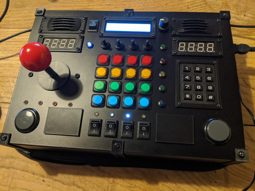
The final control surface with vinyl wrap applied and holes cut with hobby knife.
Consideration for max current across micro-controller pins
I was learning as I went here, I worried about running so many LEDs through the Arduino so after some research I managed to built a ‘component to pin’ plan that ensured each GPIO port on the Arduino would not exceed its max current. This was a job for excel. Even now I’m not sure I did this right, it’s still a bit unclear to me but I did put some fail-safes into the code to limit the number of LED and Components (inc back-lights) on at the same time.
Assembly
I covered the control panel in Matte black car vinyl wrap and started to fit the components. All components had excess wire, I figured out I would cut and fit later.
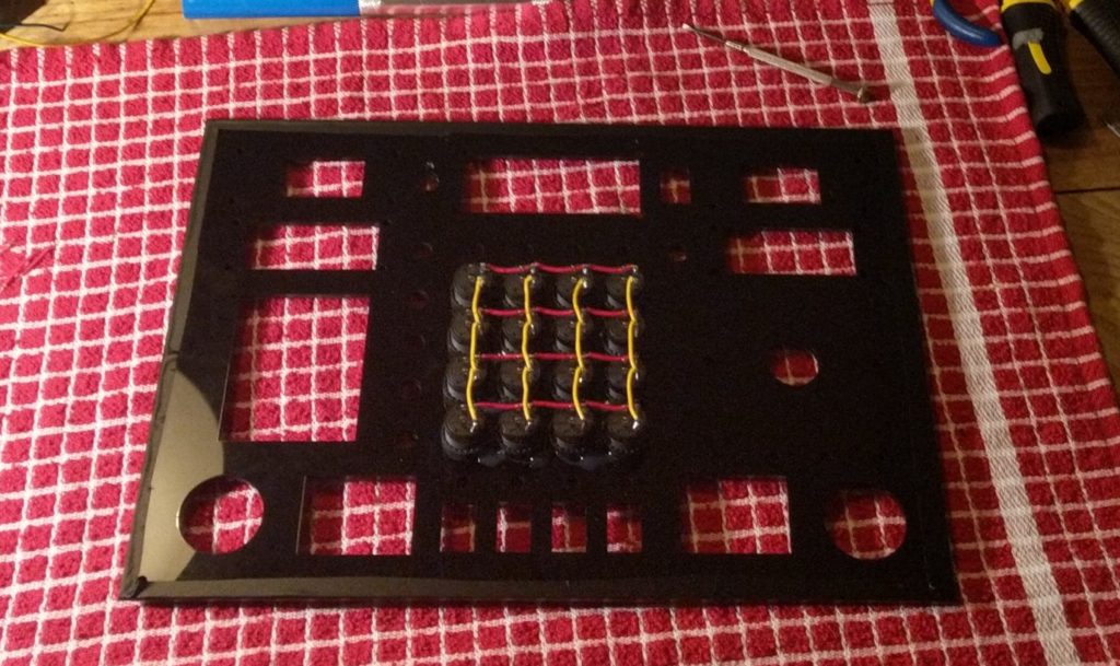
Starting to wire up the central button matrix
I still need to make a schematic of the wiring, feel free to ask an questions about all the component hookup.
I included an SD card extender so I could access the sd card via the battery compartment, the PAM amplifier was hot glued out of the way, I figured it might get warm. I also included an external power jack at the back with a switch to change between battery and mains power and also a usb port on the side so I could program once the box is finally sealed.
This was painful, the wires I used were solid core so it was a difficult fit. Got there eventually, I had to create a third ground rail internally for the 4X4 button grid. The control panel was screwed onto the box and I 3D printed brackets between the top and bottom just for appearance.
Audio
I wanted a mix of spoken word/music and sound effects to be played by the box so I hired a voice-over artist on Fiver to record a collection of word/phrases for me. I would stitch these together in code. The rest of the samples were sourced from the internet, some ripped from youtube clips (see easter egg mode)
The wavs were delivered as a single file so that meant a long time in Audacity chopping up into individual wavs and formatting. As I’d opted for full range speakers I didn’t have to worry about appply any filters to make them more audible on crap speakers.
I have just over 210 individual samples on the box ranging from simple clicks and pops, words to full CD quality kids songs and atmospheric background noise.
Unfortunately my audio board only accepted serial commands and I could never get it to send back messages. This meant I couldn’t monitor if a wav was currently playing. I had to hard code sample length and sometimes even use blocking code while samples were playing. I think this was due to my wav board having old firmware or maybe bad wiring on my side.
The Code
I didn’t have much time left before Christmas so the code is an embarrassment, but it works. Link to github at the bottom.
Script.
Incredibly simple. I had loads of memory on the Arduino Mega Clone so I don’t make use of any memory saving tricks, it’s mostly functions/for-to loops and switch statements.
The box runs 7 states controlled by the menu knob (videos are available for some of these mode below)
Simple wavs playing based on input from the control surface, animal noises & spoken words, Switch noises and the keypad reads the number and displays the digit in the displays.
Surprise! A whack-a-mole type game using the central 4X4 grid of buttons.
Snake game using joystick (with pac-man and Space-invader samples) – Removed as it was causing issues when changing modes. Need to de-bug
Simple Music Sequencer. Two Channel (notes and drum). You can switch between 4 different instruments (Piano, Organ, Synth and Acid Synth). The drums are split into Base drum, Snare, Hi Hat and Clap. Joystick controls the speed (Up.Down) and the big side buttons switch between program mode (Piano or drums). Keypad 1-4 select the instrument.
Follow-me type type game with countdown/scoring and lots of sound effects.
The Wiggles. I bought a digital copy of The Wiggle Greatest Hits, the 4×4 grid controls which song will play.
My Kids is obsessed with rockets so I’ve made a ‘rocket’ control simulator thing. And yes, I know the samples sequence do not make technical sense!
There is also an ADMIN mode for controlling the volume and a little 80’s nerd Easter egg.
Also included is a time-out that turns off all leds and sounds after a set time to save battery with a resume on any surface input.
If anybody has any deeper questions, please ask, ill include the response in the write-up.
We use cookies to ensure that we give you the best experience on our website. If you continue to use this site we will assume that you are happy with it.Ok


")

